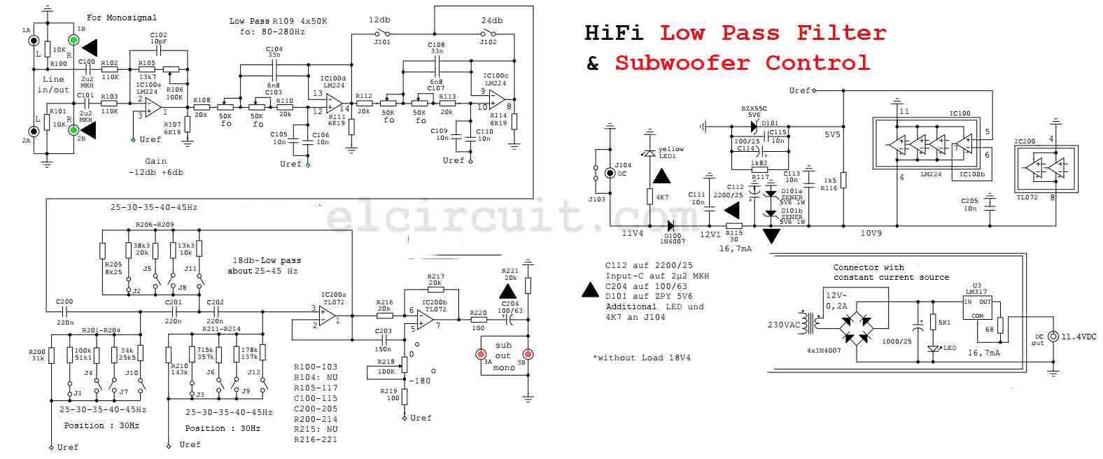
The critical applications require a design that ensures mid-frequency immune to the circuit component tolerances. The challenge involves keeping quality factor, gain and mid-frequency of the filter independent of each other. A couple of CA3080's, (IC2, 4) are actually configured to supply the adjustable gain, the resonant frequency being held proportional to the current I ABC.Narrow Band-pass filtering techniques have been a challenging task since the inception of audio and telecommunication applications. In the proposed filter design, this specific resonant frequency is linearly proportional to the gain of the two integrators. This is therefore an extremely flexible filter design, specially if the resonant frequency is featured to be adjustable. High Pass, Low Pass and band Pass from a Single CircuitĪ state variable filter such as the one shown below can generate three outputs: high pass, band-pass, and low pass. using the above simple technique you can design a reasonably good low pass filter quickly and use it for a specific application which could include a high bass music circuit, an active speaker cross over network or a home theater system etc. The resistors are all 1/4 watt rated, 5% or 1%.

The voltage spec may be selected to be twice that of the supply voltage used. The values of Cin and the Cout shown in the single supply low pass filter are not critical and these can be anything 100 to 1000 times that of C1, meaning if you selected C1 as 0.1uF, then these could be anywhere between 10uF and 100uF etc. Here the "frequency" is the range where the cut-off transition is expected to happen, or the desired cut-off range. R1 or R2 = 1 / 2 √2 x π x C1 x Frequency. R1 and R2 can be identical, and can be calculated using the following formula: Next, we can calculate C2 with the formula: The components R1, R2, and C1, C2 configured with the non-inverting (+) and the inverting (-) input pinouts of the opamp basically decide the cut-off range of the filter, and these need to be calculated optimally while designing the circuit.įor calculating these parameters and designing a low pass filter circuit quickly within minutes one can utilize the following formulas and the explained steps:įirst we need to find C1 which we can do by selecting any value arbitrarily as per our convenience. Designing a Customized Low Pass Filter Circuit The first one needs to be powered by a dual supply, and the second one works using a single supply voltage. The following images depict the standard opamp based low pass filter circuits. The following graph provides the typical low pass filter frequency response with regards to the gain, we can clearly see how the response attenuates (gradually drops) as the frequency increases past the particular cut-off threshold.

Normally opamps are employed for making such filter circuits, since opamps are best suited for these applications due to their extremely versatile characteristics. How Low Pass Filters WorkĪs the name suggest low pass filter circuits are designed to pass or conduct a preferred range of frequency lower or below a desired cut-off threshold, and attenuate or gradually block the frequencies above this value. The above discussions shows how simply anybody can calculate and design a high-pass filter circuit quickly for a particular application which could be a treble control circuit, a 10 band graphic equalizer or a home theater circuit etc. The single supply version of the high pass filter circuit can be seen involving another capacitor Cout which is not at all critical and can be approximately 100 or 1000 times more than C1. Here the term "frequency" refers to the desired high-pass cut-off threshold below which other unwanted frequencies need to be attenuated or ignored gradually.įinally, calculate R2 in the same way as above using the following equation: Next, calculate R1 by using the following formula:
#Low pass filter designer how to#
How to Design a Customized High Pass FilterĪs proposed, to design a high-pass filter circuit quickly, the following formulas and the subsequent steps can be used for calculating the relevant resistors and capacitors.įirst, select an appropriate value arbitrarily for C1 or C2, both can be identical. In both the above configurations, the opamp forms the central processing active component, while the associated resistors and capacitors wired across the input pins of the opamp are introduced for determining the high-pass filter cut-off point, depending upon how the values of these passive components are calculated as per the users specifications or requirements. The following two images are configured as standard high-pass filter circuits, where the first one is designed to work with a dual supply whereas the second one is specified to operate with a single supply.


 0 kommentar(er)
